30 August 2024
A slight change in the order of our development updates as we want to save the most complex area for last. Today, we will look at the overhead panel.
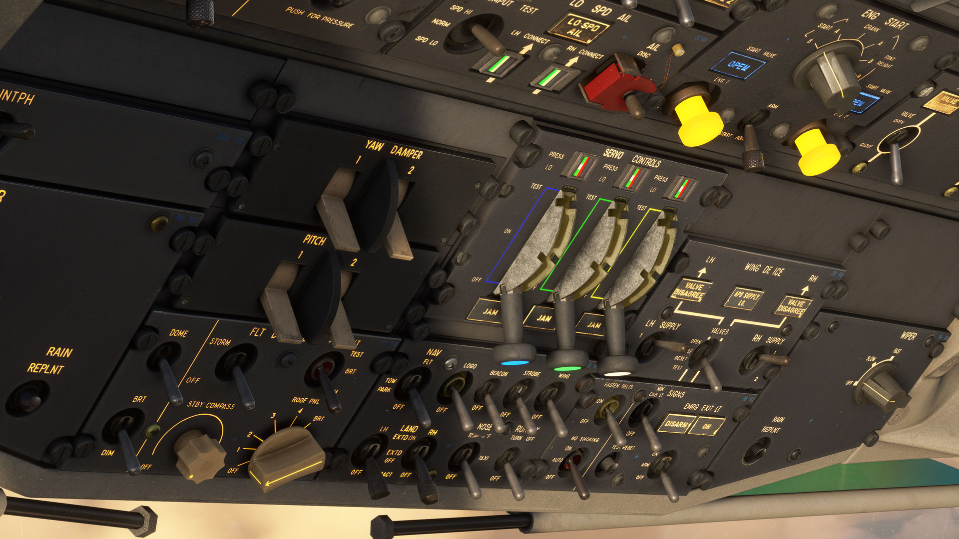
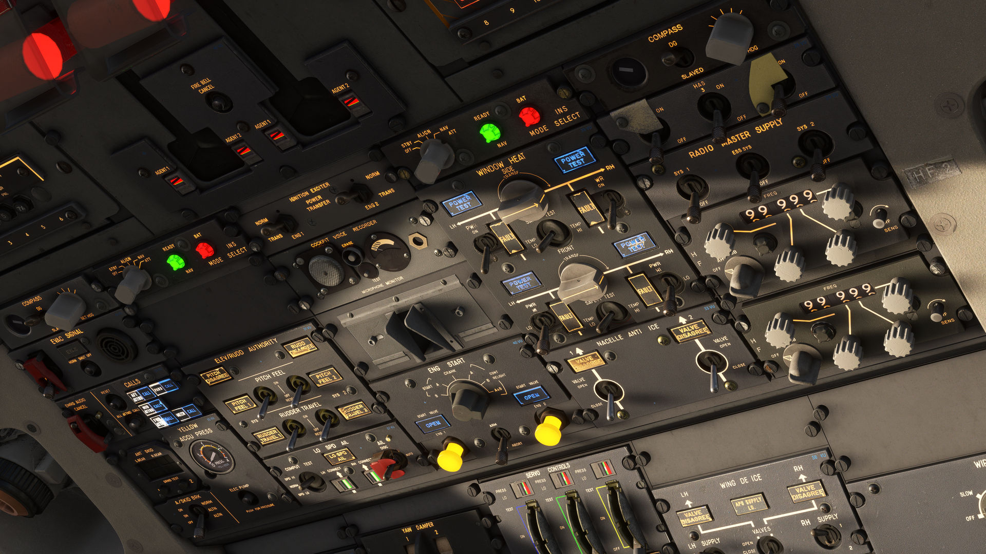
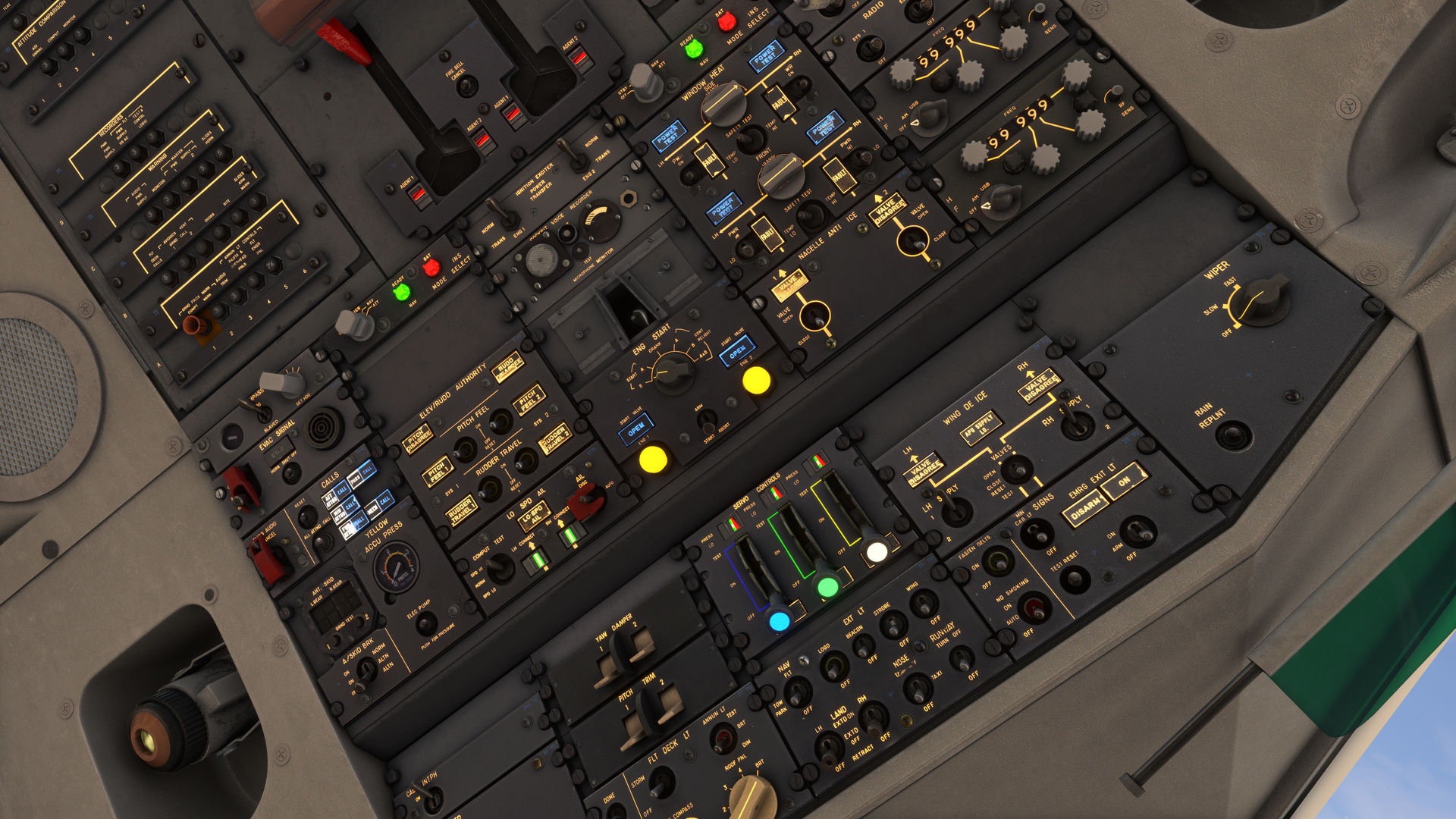
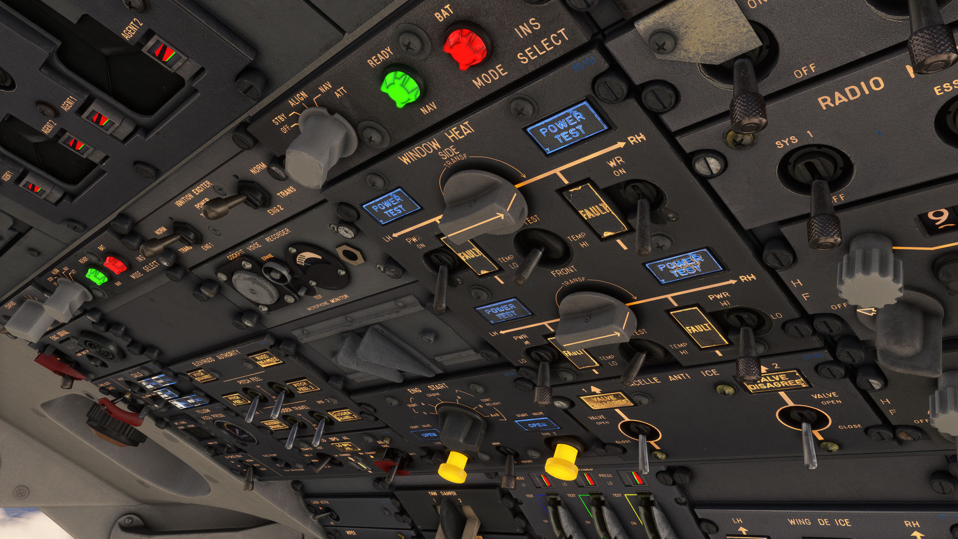
The overhead of the A300B4 is home to a mixture of different systems, and its design philosophy is such that some controls which could have been housed on the engineer’s panel are instead found on the overhead. This is because when the aircraft was designed, Airbus was already thinking ahead to the idea of two-crew cockpits, enabling it to be operated temporarily by two crew members and with the intention of certifying the aircraft for two-pilot operations permanently.
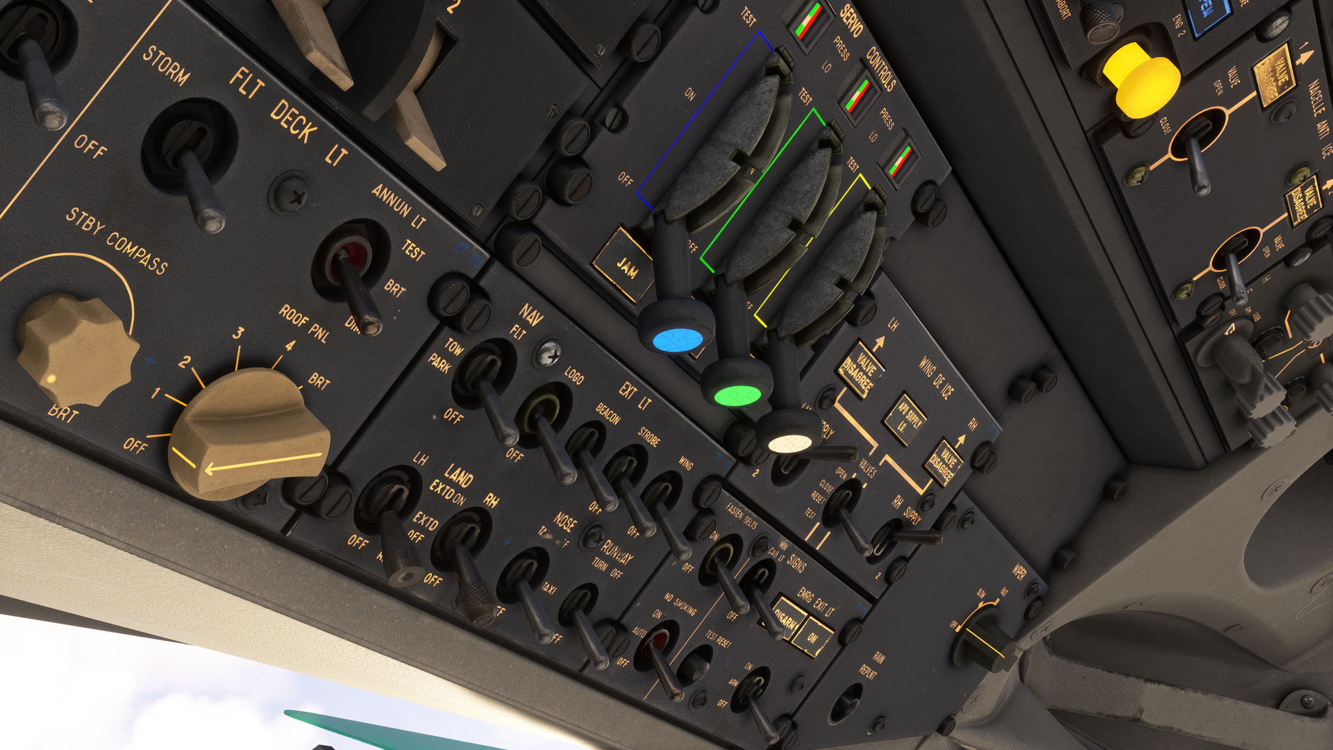
Unlike later Airbus models, we still have a rather chaotic array of switches, knobs, and annunciator lights typical of aircraft of the era. Despite this and after some studying, everything does begin to make sense. The layout is reminiscent of modern types, with the exterior lighting and passenger signs positioned at the very front and switches for de-icing within easy reach. There's some oddities such as the HF radio's being positioned here instead of on the pedestal, with the other comms radios. One of those systems which could belong to the engineer’s station are the three prominent servo control levers which the pilots can switch in case of a control surface valve jam.
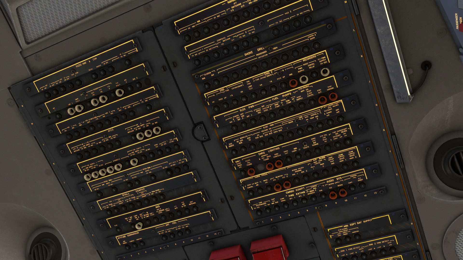
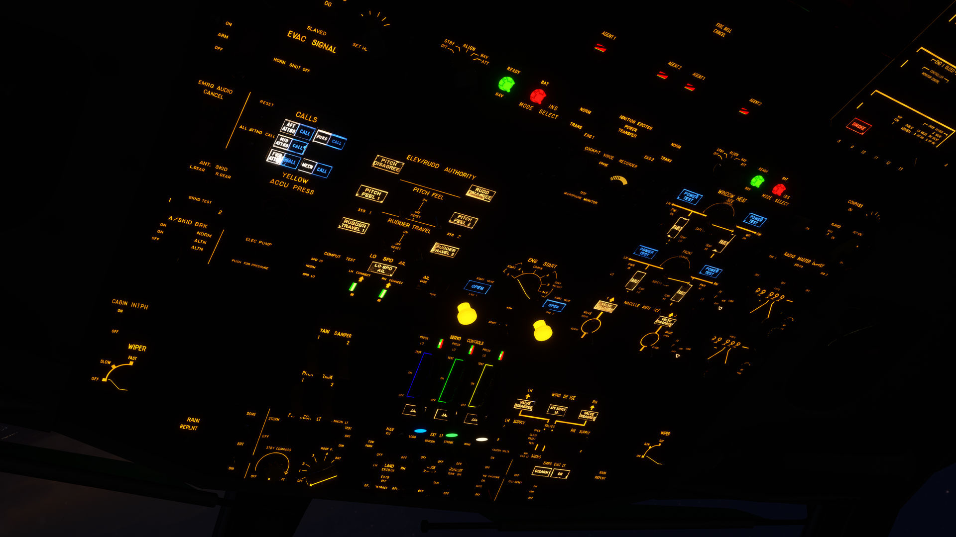
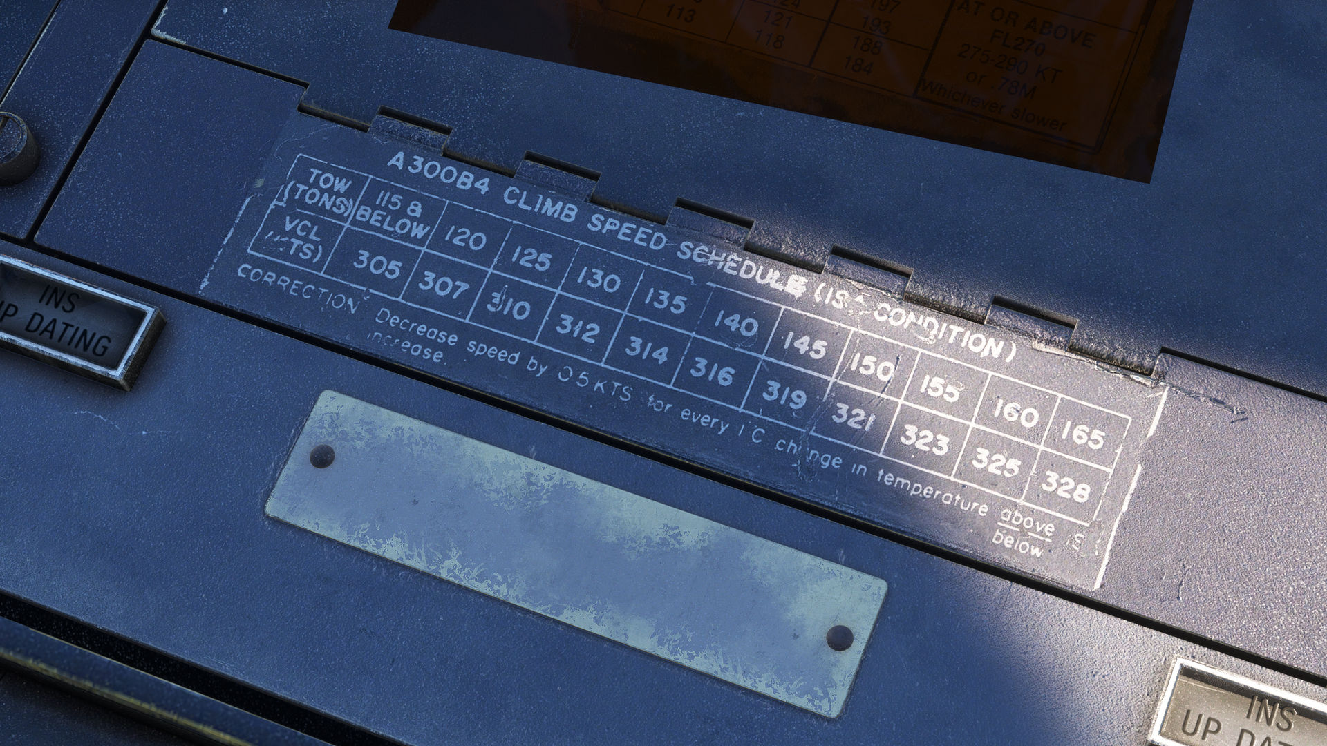
Each panel is clearly labelled, schematics are provided where necessary, and the annunciator lights are colour-coded to represent varying levels of warning and indication. A type of mechanical indicator you may spot are the magnetic indicators abbreviated to M.I. We’ll become more familiar with these when we move to the engineer’s panel, but suffice to say the rotating drum of these have been modelled, gone are the days when we had to use 2D textures.
As with the areas of the flight deck that we have already seen, every single object has been textured individually to give the most realistic wear and tear possible. All text and schematics use decals to enable the best clarity whatever your settings.
We hope you enjoy the screenshots below. Next time, we will preview the engineer’s panel.
08 August 2024
In this development update, we'll give you a short tour of the A300B4’s main instrument panel via the text and the screenshots below.
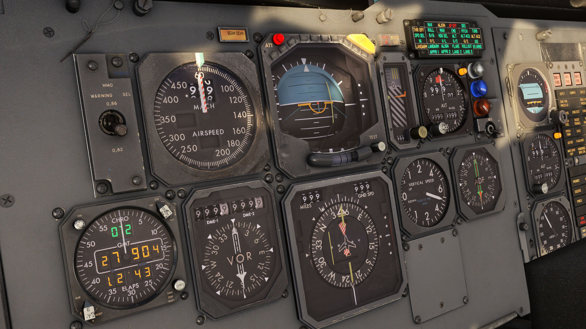
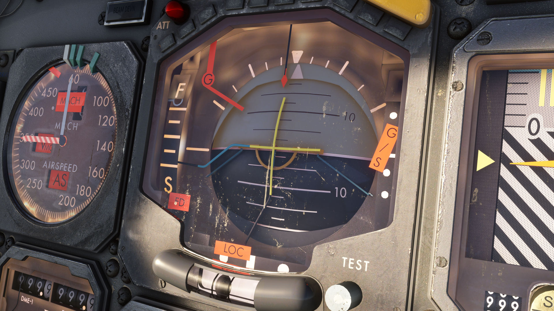
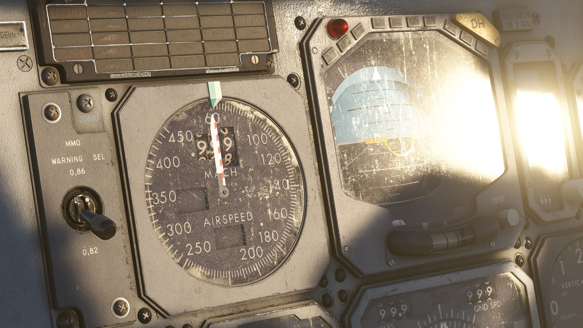
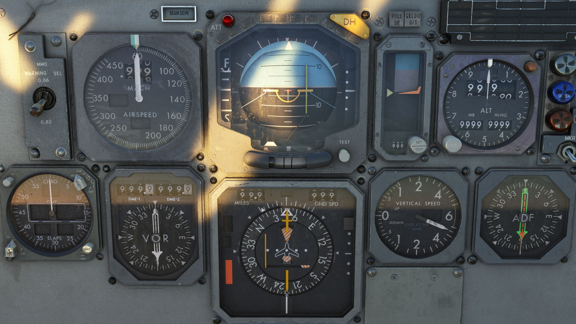
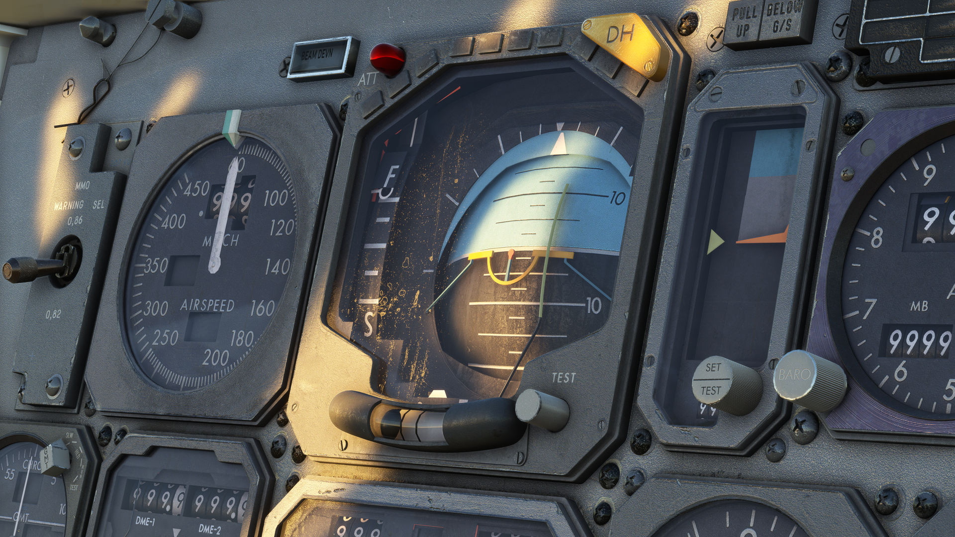
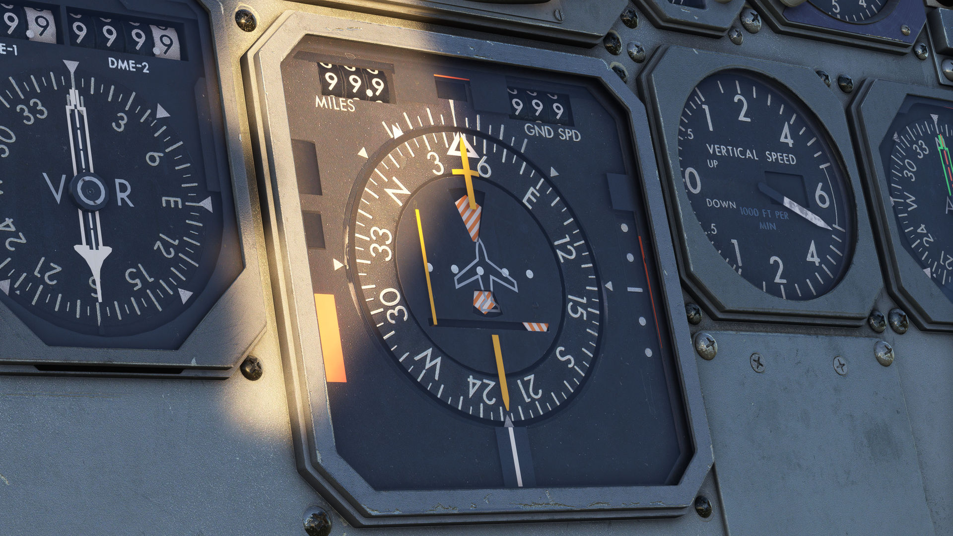
The first thing that immediately stands out is the large blue and black Attitude and Director’s Indicators (ADI’s). These characterise the A300B4’s flight deck design, being extremely clear and logical. Surrounding the ADIs, you’ll find a suite of familiar flight and navigation instruments, equally well-designed. Our artist has taken the greatest care in modelling these with as much detail and accuracy as possible, with textures directly created from real-world photos. This ensures that the scales and fonts are exactly as found on the real-world aircraft. Every single digit, needle, and flag is modelled and animated, right down to the tiny wires that hold the warning flags in place.
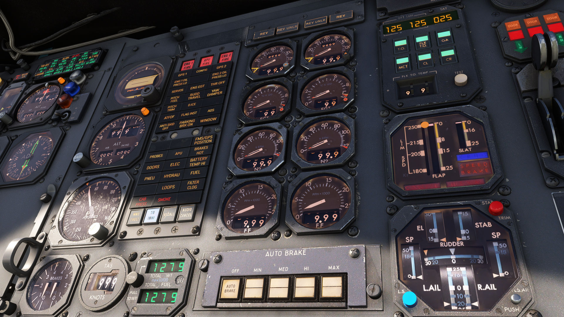
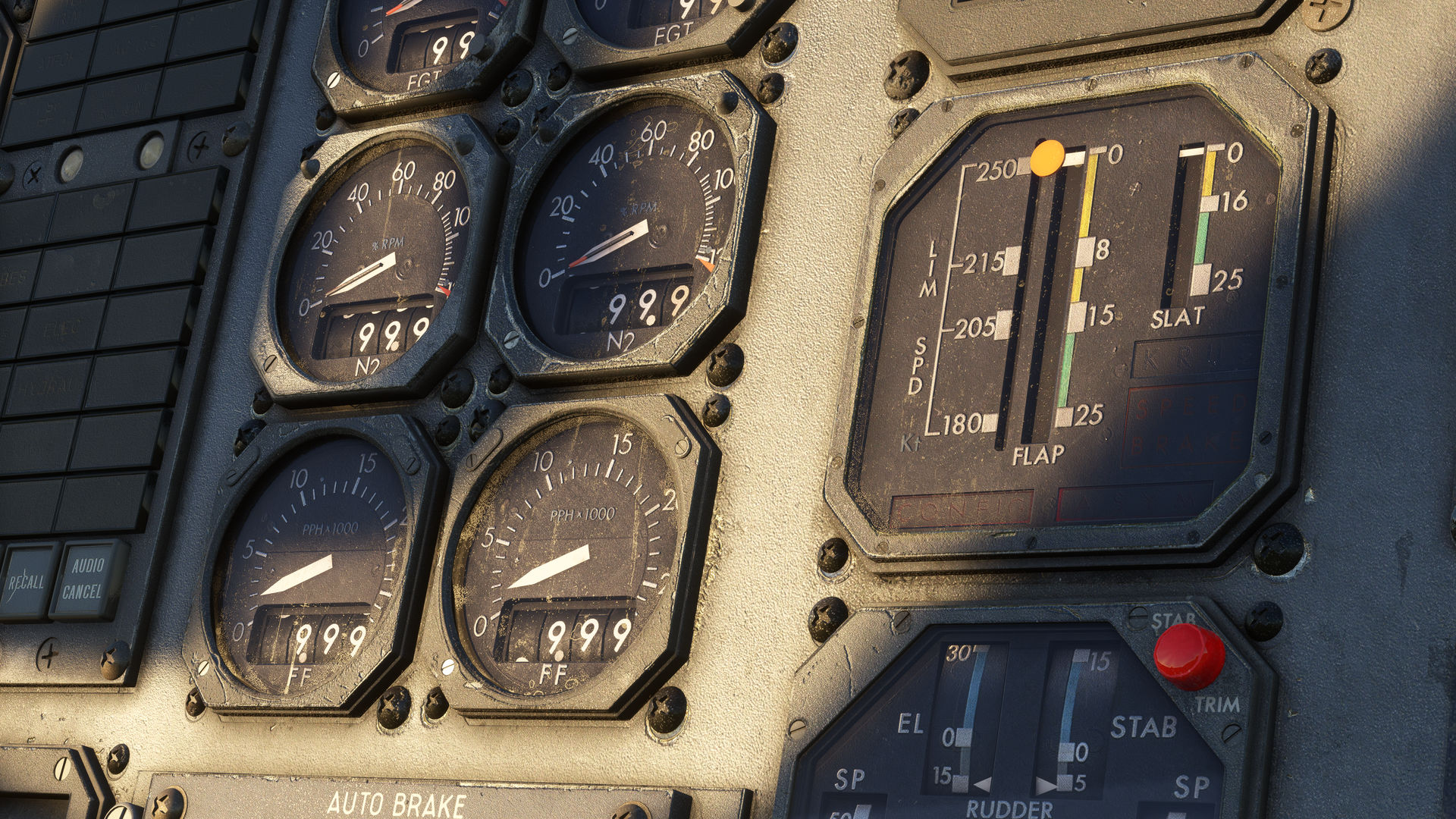
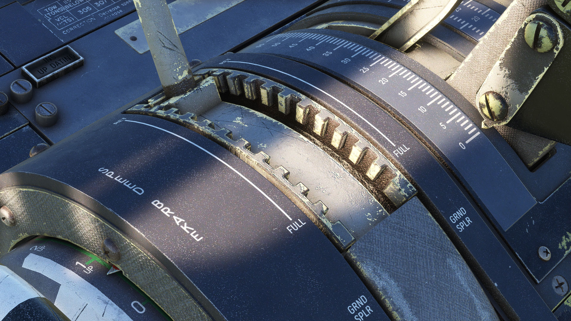
Dominating the centre instrument panel are the engine instruments and the Master Warning Panel. Notice how each caption has its own level of wear, and how the text is inconsistently lit. We hope you agree that this attention to detail creates an authentic feel of an imperfect and used aircraft. Located on the centre panel are standby gauges, the N1 limit computer, mechanical indicators for the flap and flight control positions, the landing gear lever, and the autobrake selector buttons.
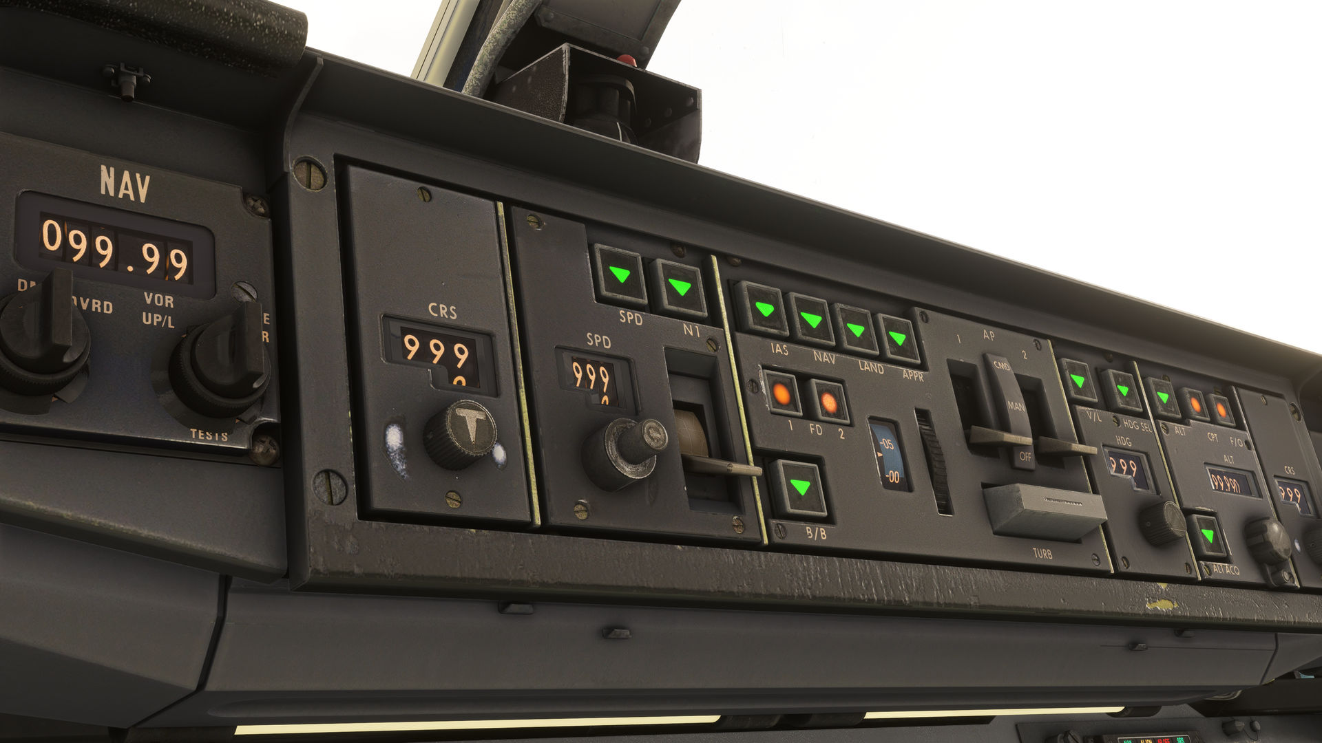
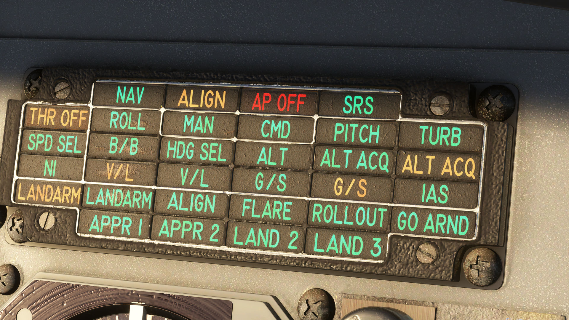
Moving up to the glareshield, we see the controls for the Flight Director/Autopilot and Autothrottle, known as the Automatic Flight Control System (AFCS). The panel is made up of white piano key-style levers for the master switches, large pushbuttons that illuminate when a mode is selected, and selector knobs with mechanical drum window displays for selections such as altitude and airspeed. Notice how we’ve textured each object individually, with each button having individual wear and tear. Our last stop is the colourful grid of captions below the AFCS panel, known as the Flight Performance Indicator (FPI), this displays the armed or active modes selected on the AFCS panel, something you’ll need to monitor closely when you get to fly our A300B4 Professional!
We hope you enjoy the screenshots below, next time we will take a closer look at the engineers panel.
23 July 2024
Here’s the first of a few new updates covering the latest visual work that has been carried out on the Flight Deck area.
Over the past few months, our Lead artist has been busy recreating the remaining sections of the A300B4’s complex cockpit—a mammoth task when you consider each individual gauge and needle in this 1970’s mechanical beast. Our artist has also taken great care to give the aircraft an authentic, lived-in feel, with each panel, knob, and screw having its own individual level of weathering and discolouration, faithful to the real-world reference aircraft.
With this work now complete, we are excited to share the results with you. Through a series of In Development updates, we are excited to take you on a tour of the entire flight deck, starting with the centre pedestal.
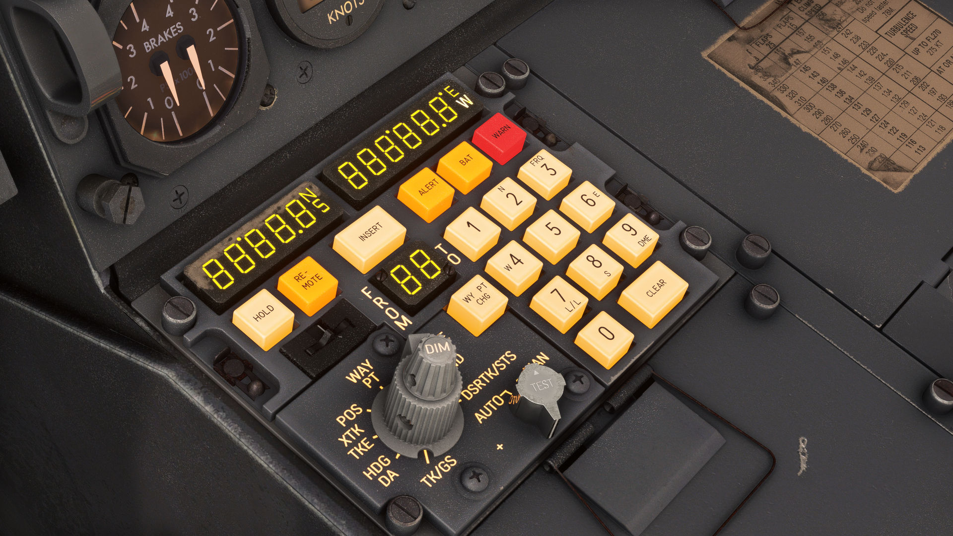
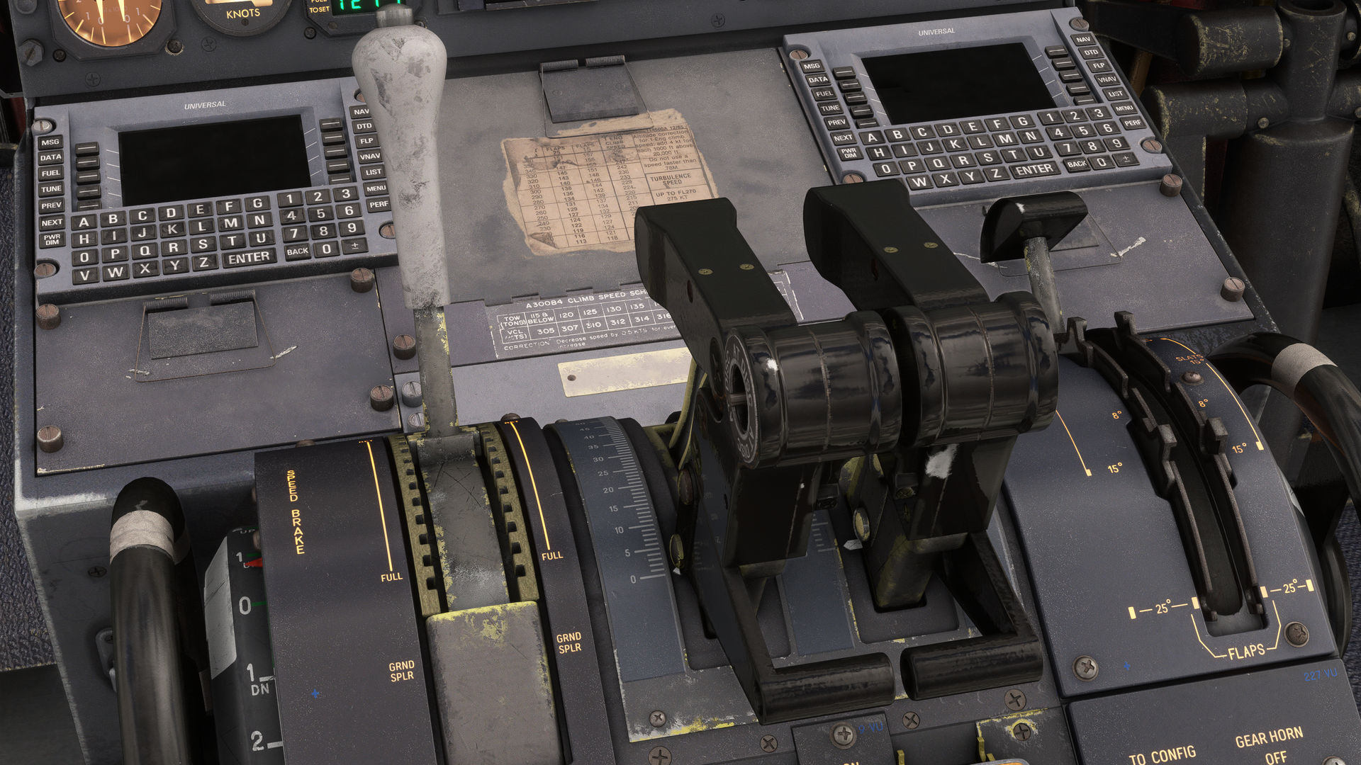
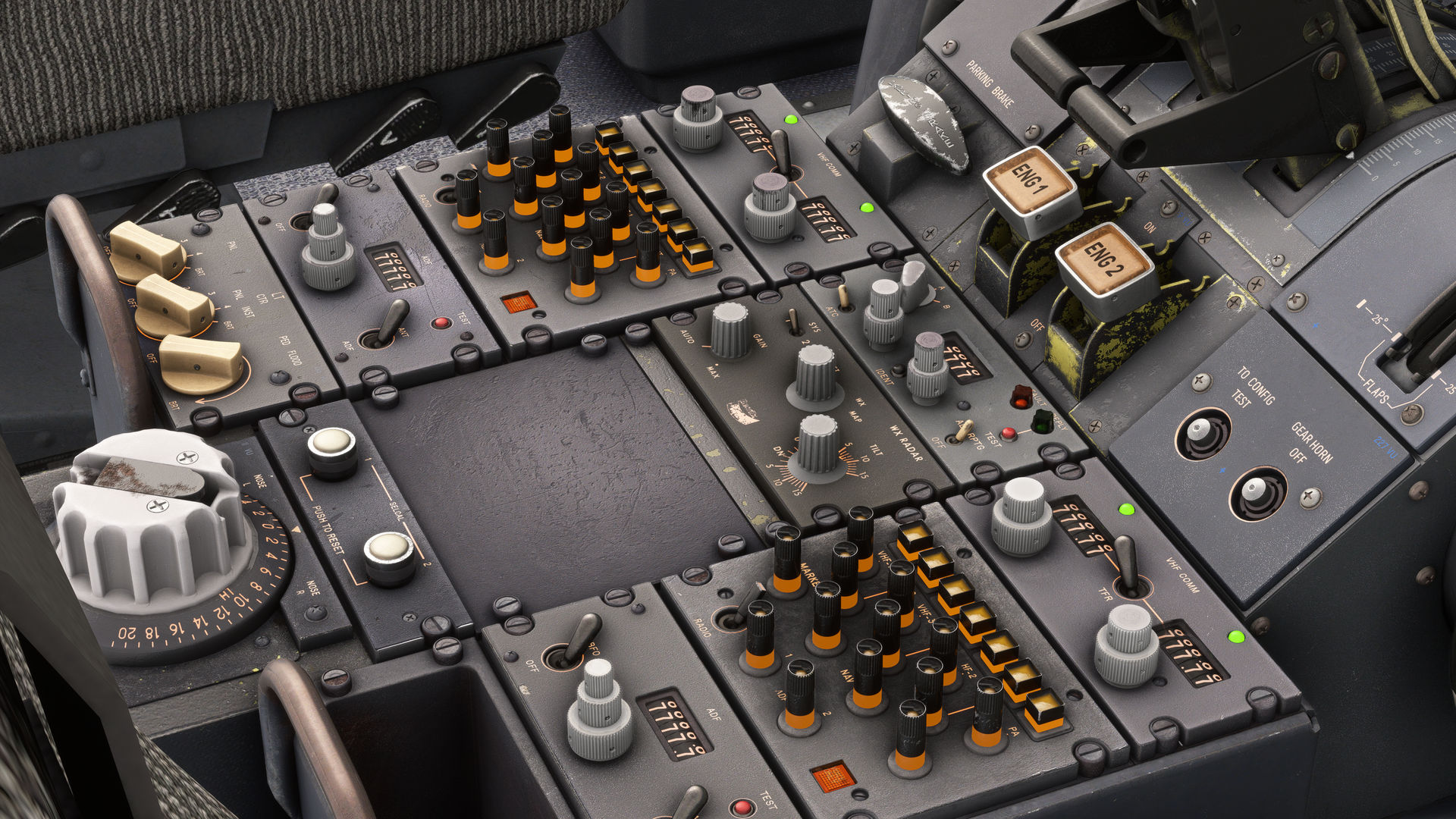
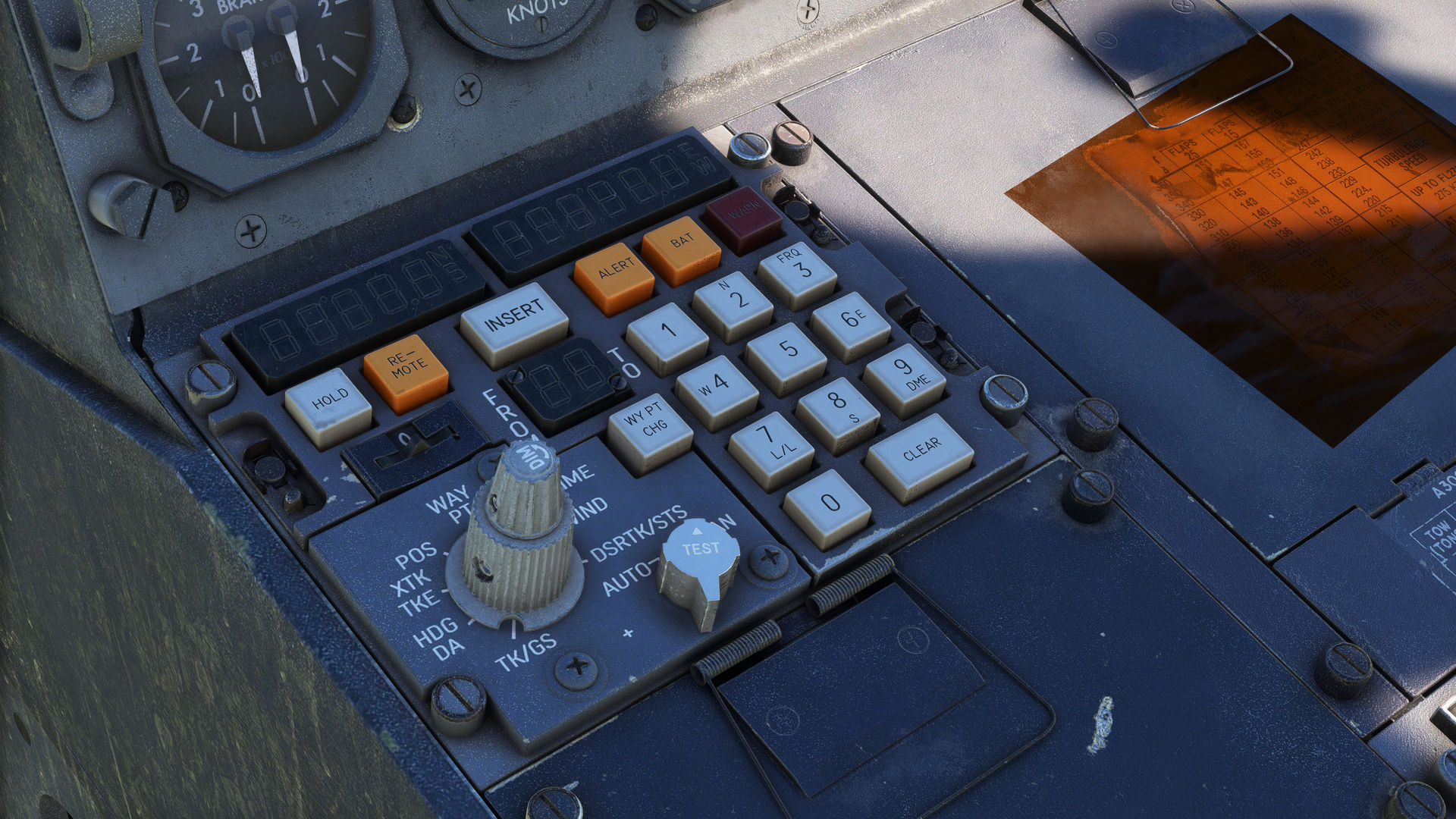
Starting at the forward section, you’ll notice the authentic recreation of the Carousel IV Inertial Navigation System’s (INS) Control Display Unit (CDU) on either side. Each segment of the data displays has been created using its own object to give an authentic and crisp look from any distance. For a more modern option, you will be able to swap these for the UNS-1 FMS, which were often retrofitted to real-world A300’s.
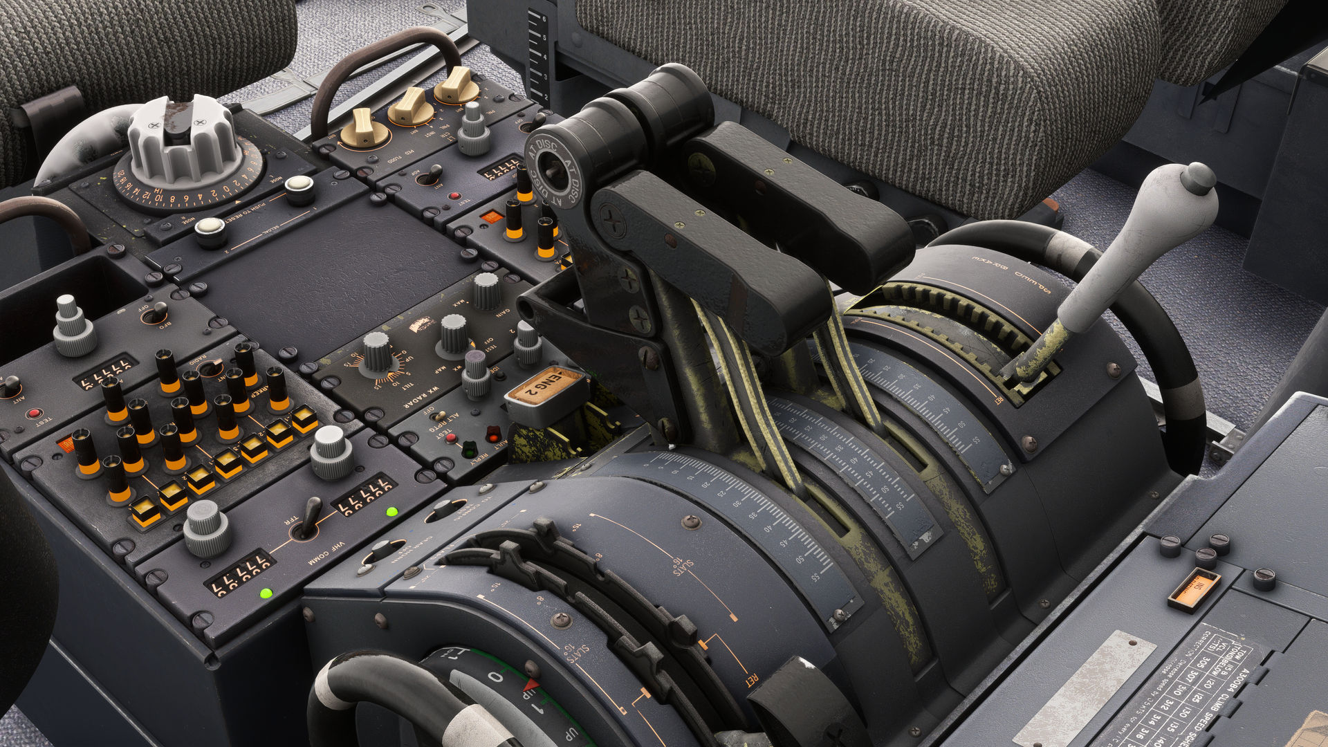
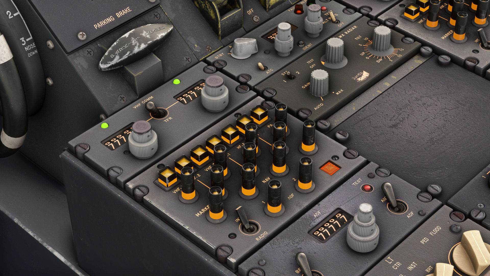
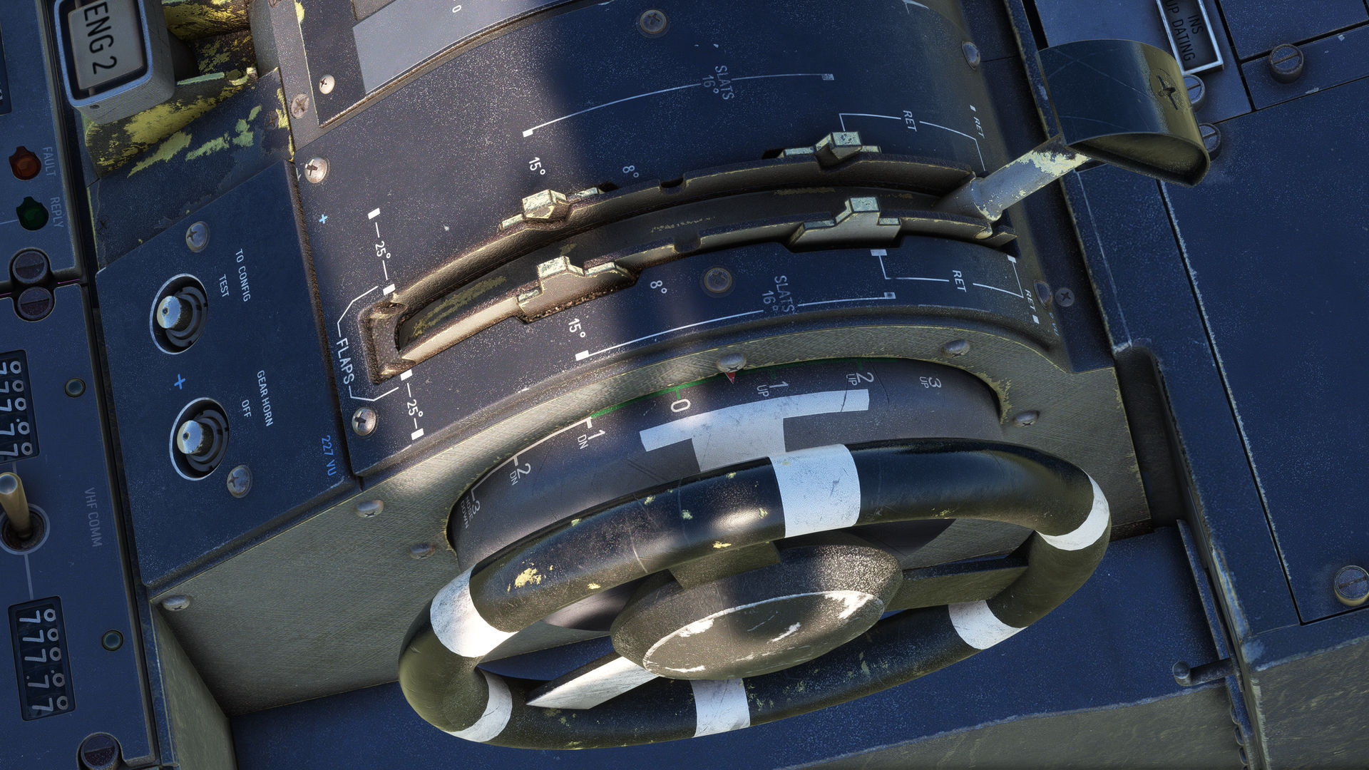
Moving rearward, attached to either side of the pedestal, we find conventional stabilizer trim wheels with a simple pointer and scale from 3 degrees nose down to 12 degrees nose up. On the top, we find a large speedbrake lever and a combined flap/slat lever with 5 positions. In the middle we find two conventional throttle levers, and yes, we mean proper throttles rather than the gated “Thrust Levers” that we find on later Airbus families. Aft of these, we have the fuel cut-off switches, parking brake handle, and a couple of buttons for the take-off config test and gear horn warning.
Moving further aft, we have the heart of the A300’s communications suite. This comprises 2 VHF control units with a transponder unit in the centre. These all feature mechanical rotating drums that we have individually modeled. Behind, we have 2 audio selector panels and controls for the weather radar located in between. Located behind both audio selectors, we can find our ADF navigation radios, again with rotating mechanical displays. Behind the ADF1 panel, we can find 3 white knobs which control the various lighting of the centre pedestal. Coming towards the rear, we have a SELCAL controller, and finally, the two large knobs located on the top and rear are for the rudder and aileron trims.
In summary, the centre pedestal has quite a conventional layout that we are used to seeing on more modern types; however, there is character made up by the mechanical displays and vastly different wear and tear where the units have been swapped out over the lifetime of the aircraft.
We hope you enjoy the screenshots below. Next time, we will focus on the forward panel and autopilot.
19 December 2023
Since the reveal of our A300B4 Professional at FS Expo 2023 our talented artists has been busy taking on the mammoth task of texturing the rest of the flightdeck and upgrading the exterior model.
To the cockpit where every single panel, gauge, knob and lever is being painstakingly recreated to match the real aircraft. Right down to the weathering on each individual screw head we aim to bring a level of detail never seen before in Microsoft Flight Simulator.
On the exterior our artist has reworked most of the fuselage and nose section, countless new details have been added including highly detailed flap track mechanisms and brand new highly detailed models for the CF6 and JT9D engines.
Meanwhile we have made excellent progress with the systems coding, with the Electrical, Air Bleed, Air Conditioning and Pressurization, APU and Fuel systems complete. These have all been custom coded so that all valves, temperatures and pressures will react as in the real world and are affected by environmental conditions and system configuration. Next up is the Hydraulic system.
We look forward to sharing more details and screenshots early next year.